
Good engineering judgement comes before specialised software.
One of the most common questions I receive from our piping training course attendees is:
When do we need a full pipe stress analysis for a project?
The answer is not simple.
Some piping systems can be designed confidently using sound engineering principles, pressure rating calculations, support span tables and practical experience. Others require a detailed flexibility analysis using specialised software such as Octave Aspect Pipe Stress (formerly known as CAESAR II) or AutoPIPE.
Knowing the difference is an important engineering skill. A detailed stress analysis can add significant value where it is warranted, but it also consumes time and money. Equally, deciding not to undertake a stress analysis without understanding the risks can lead to expensive failures, excessive nozzle loads or fatigue cracking later in the asset’s life.
Engineering workflow comes first
Before considering a flexibility analysis, the piping system should first be designed using fundamental engineering principles. Fig. 1 shows a typical engineering workflow for pressure piping design (noting that it is not a prescriptive design procedure but a generic guide). Notice that pipe stress analysis is one of the final design checks—not the starting point of the design process.
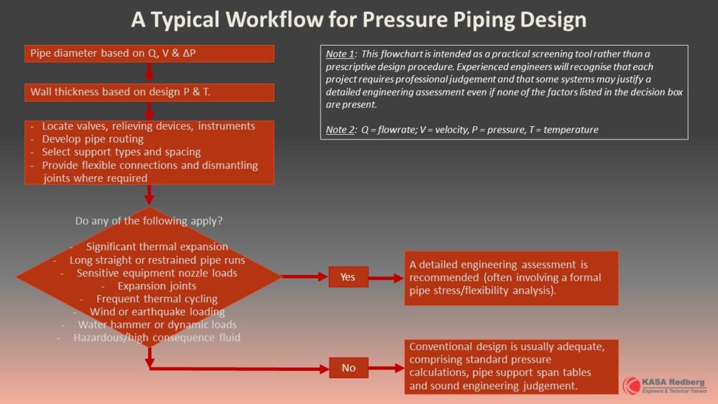
Fig. 1 Typical engineering workflow for pressure piping design
Good piping layouts often eliminate the need for complex stress solutions. Small changes such as relocating an anchor, introducing a change in direction, shortening an unsupported span or using a flexible final connection to sensitive equipment can dramatically reduce stresses before any software analysis is required.
Basic mechanical design is often sufficient
Many industrial piping systems never require a formal flexibility analysis. Typical examples include relatively short ambient-temperature water pipelines, pump station pipework, buried pipelines and simple utility services with adequate supports and good inherent flexibility. For these systems, engineers commonly rely on:
- Pressure rating calculations.
- Pipe support span tables.
- Good support detailing.
- Practical routing.
- Sound engineering judgement.
This approach has been successfully used throughout industry for many decades. The Australian water industry and the Australian mining industry are homes to many of these systems.
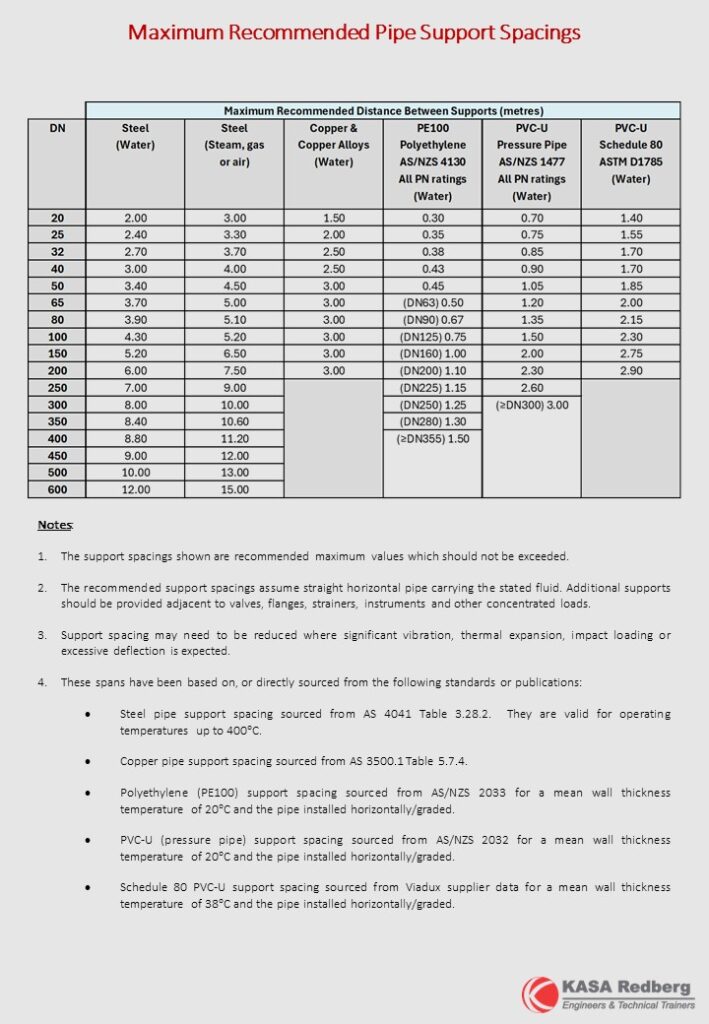
Fig. 2 Extract from KASA Redberg’s pipe support span tables
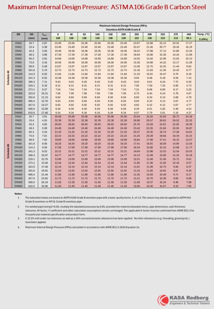
Fig. 3 Extract from KASA Redberg’s allowable pressure tables
What actually causes piping failures?
One misconception is that pipes usually fail because the calculated stress exceeds the allowable stress specified in the piping code. In reality, this is relatively uncommon.
Long before a well-supported pipe reaches its allowable longitudinal bending stress, excessive sagging, deflection or vibration is often visible during operation. In practice, many piping problems arise from other mechanisms, including:
- Thermal expansion and contraction.
- Thermal fatigue from repeated operating cycles.
- Water hammer and other transient hydraulic loads.
- Wind loading on exposed pipework.
- Earthquake loading in seismic regions.
- Excessive loads transferred into pumps, vessels or tanks.
- Fatigue at stress concentration points such as elbows, fabricated branch connections and tees.
These are often the issues that determine whether a detailed stress analysis is worthwhile.
Equipment nozzle loads are often the deciding factor
One of the first questions that should be asked is:
What is the pipe connected to?
Rather than:
What is the stress in the pipe?
It is very easy to get caught up in colour-codes stress plots which are provided by pipe stress analysis software, but the nozzles and connected equipment will typically be the “weakest link” in many systems. Also, the type of equipment is important. For example, a steel pressure vessel is generally capable of resisting significantly higher nozzle loads than a polyethylene storage tank or a steel panel tank.
Where lightweight equipment is involved, the objective is often not to make the piping stronger—but to make it more flexible. Practical solutions may include:
- Changes to the pipe routing (i.e. directional changes) by allowing an offset leg to “take up” the thermal expansion in a pipe run.
- Flexible rubber expansion joints.
- Flexible metallic expansion joints where appropriate.
- Braided stainless steel or rubber hoses.
- Polyethylene pipe spool pieces.
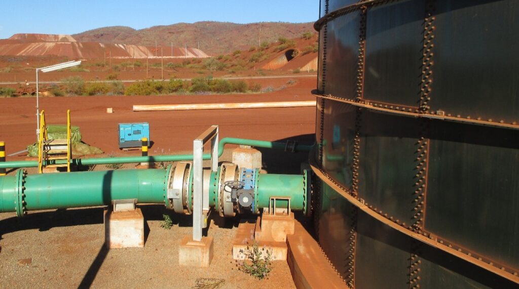
Fig. 4 Pipework (with expansion joints) connected to a steel panel tank
In Fig. 4, the expansion joints are not there to protect the pipe. They are there to protect the tank wall from thermal expansion loads.
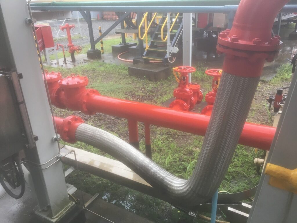
Fig. 5 Braided stainless steel hose provides a more flexible piping system
When does a detailed stress analysis become worthwhile?
A formal flexibility analysis should be seriously considered where one or more of the following conditions exist:
- Significant thermal expansion due to operating temperature or environmental temperature changes.
- Long restrained pipe runs.
- Critical equipment with strict nozzle load limitations.
- Pressure vessels, heat exchangers or turbines.
- Frequent thermal cycling.
- Expansion joints requiring calculated anchor and guide loads.
- Significant wind or seismic loading.
- High consequence fluids or hazardous service.
- Complex pipe racks with multiple restraints.
- Long above-ground pipelines exposed to large day/night or seasonal temperature variations, even where operating temperatures are relatively low.
Under these conditions, specialised piping stress software allows engineers to predict much more than simply pipe stresses. A detailed analysis can also evaluate:
- Equipment nozzle loads.
- Anchor loads.
- Support reactions.
- Thermal displacements.
- Guide forces.
- Expansion joint movements.
- Fatigue due to thermal cycling.
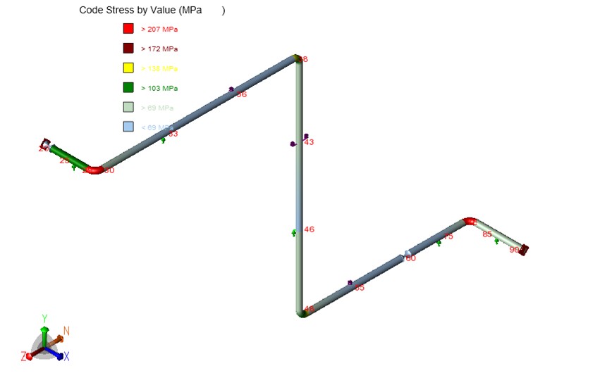
Fig. 6 Example colour coded stress plot using pipe stress analysis software
The software itself is not the solution. It is simply a productivity tool that enables engineers to more efficiently verify that the piping system will behave as intended under all anticipated loading conditions (when compared to performing hand calculations).
Engineering judgement remains the most important tool
Pipe stress analysis software is an invaluable engineering tool, but like any engineering tool, it should be applied where it adds genuine value. Many piping systems can be successfully designed using sound hydraulic design, appropriate material selection, pressure calculations, support span tables and practical engineering judgement. However, once significant thermal movement, equipment nozzle load limitations, expansion joints or occasional loading become important design considerations, a detailed flexibility analysis often becomes a worthwhile investment.
The real skill lies not in knowing how to use stress analysis software. It lies in knowing when it is needed.
Interested in learning more?
These practical engineering decisions are discussed in detail during KASA Redberg’s training course titled:
Piping Design to AS 4041 & ASME B31.3
This course is run by KASA Redberg as a live-streamed, instructor-led training course delivered via Microsoft Teams every August. Alternatively, it is also available as an in-house, private course at your place of business. Contact us for further details or view our dedicated webpage for this course.